LoconTroller LT150A
150A Continuous fully integrated locomotive control system with sound and light control.
  • Full Bridge motor control with 150A continuous operation
  • Lighting controller with Front, Rear, Ditchlight channels, and 3 switchable Auxiliary channels
  • Fully integrated DCC capable sound system with 100W Class D amplifier
  • Large set of Telemetry for complete control.
  • Bi Directional Link Radio control with up to 1 mile (line of sight) range.
  • Many deadman features for security
  • Direct to locomotive teathering of remote for recharging / control
 
Downloads:
Manual
Installation Guide
Remote Control
Direct To Locomotive Teathering:
• Optional communication board enables direct-wire communication from handheld to locomotive via MU ports.
Deadman Features:
• User configurable modes and options:
• Button hit timeout with adjustable delay timer
• Remote movement detection utilizing accelerometer
• Free-fall detection utilizing accelerometer detects dropped remote control
• Brake button hit while locomotive speed > threshhold value
• Shutdown on power-off or loss of communication
• Shutdown communicated to all MU locomotives
Power Requirements and Specifications:
• Up to 10 hours operation from 2 AA NiMH 2300mAH cells.
• Integrated charger can charge from any 12V source.
• Transmitter can charge from locomotive MU ports.
• Charge status LED indicates mode of charge operation.


Radio:
• Bi-Directional link
• High speed 2.4Ghz spread spectrum communication
• Line of sight range up to 1 mile
• Error detection and correction
• Loss of signal shutdown response of <= 0.5 seconds.
Graphical Display:
• 128x64 pixel Monochrome LCD.
• Speed of locomotive in scale and actual miles or kilometers per hour + odometer
• Battery voltage of 2 , 3 , 4 or 6 batteries ( 24V to 36V)
• Current draw from motor drive
• State of charge of locomotive batteries
• State of charge of handheld battery.
• Optional motor temp or slipping indicator for motors.
• Indication of motor fuse blown
• Brake pressure for air brakes (locomotive and/or train) when applied
• Battery and health status of MU connected Locomotives.
Button Controlled Functions:
• Speed and Direction.
• Application and associated pressure for locomotive brakes or train brakes or both.
• Horn
• Bell
• Individually controlled front and rear headlights. On/Off/Dimming
• Ditch lights ( can be turned on, off, dimmed, and auto triggered by horn)
• Alt function key to access auxiliary lighting controls for mars, numberboards or beacon lights
• Sound volume up and volume down
• Inbuild flashlight for night running


Controller Specs
Telemetry:
• Up to 3 batteries in sections of 12V , up to 6 batteries in sections of 6V
• Total System Current (Motor control + Accessories)
• Motor control current
• Speed
• Brake pressure x2
• Temperatures x4
• Slipping / Fuse blown detection
Brake Controls:
• 2x connectors for train and locomotive brakes with valve control (up to 1A) and pressure sensur return inputs.
• Air brake control system requires valve/motor drive/sensor box
• Works with both positive air pressure and vacuum brake systems.
• Controls air pressure to brakes in PSI direct from hand held remote command


Misc Specifications:
• Power from 24V or 36V Lead acid batteries
• 200A maximum current input combined motor+accessories
• Under Voltage protecion threshold at 20V
• Motor PWM frequency of 16khz
• Headlight/Ditch light lighting via CC-CV controller/regulator. Adjustable current and voltage. 3A max. Each output. internally limited
• Internal accessory bus protected via thermal breakers
• Speed detection via Hall effect sensor or reed switch input. Requires sensor installation and magnets on one wheel

 
Motor Control:
• Up to 150A continuous operation
• Integrated mains contactor with pre charge circuit eliminates chassis wiring.
• Integrated passive cooled heat sink.
• Regenerative braking/four quadrant control
• Full bridge circuit eliminates relays in directional control.
• Thermally Protected
• Undervoltage Protection
• Overvoltage Protection (50V max)
• Reverse Protection
• Motor to (+) and Motor to ground short detection.
• Current hard limit fixed at 170 Amps
• User adjustable current soft limit


Lighting Controls:
• Forward and Reverse headlights with dimming and selectable drive for LED or up to 40 watt of incandescent lighting
• Ditch lights with dimming and selectable drive for LED or up to 40 watt of incandescent lighting.
• Ditch lights can be triggered with horn.
• Auxiliary switched fixed 12V (1A max) for controlling a mix for lighting or external horn and bell

Sound Controls:
• Integrated 100Watt (peak) class D amplifier provides ample drive for 6 and 8 ohm load.
• Integrated DCC controller permits use of most any DCC sound board on Address 3 to control horn , bell and prime mover sound
• User choice of 3rd party sound boards mountable in specially made internal compartment of the controller housing.
• throttle controls sound rung independently of motor control setting to improve timing of prime mover sound and actual locomotive speed.
• Volume control circuit independent from used sound module
• 3 Auxiliary switched fixed 12V (1A max) ouputs for controlling a mix of lighting or external horn and/or bell (configurable via remote control menu)

Connection Overview
1. Main power connection
2. Motor connections
3. Audio output
4. Multi unit connector
5. Train Brake connector
6. Locomotive Brakes connector
7. External Signal connector
8. Main System connector
9. Sensor input connector
10. Radio transceiver connector
11. Speed and Slips sensor input
12. 12V continuous and Switched Auxiliary connector
13. Lights connector
14. System LED panel (on top)

Durability

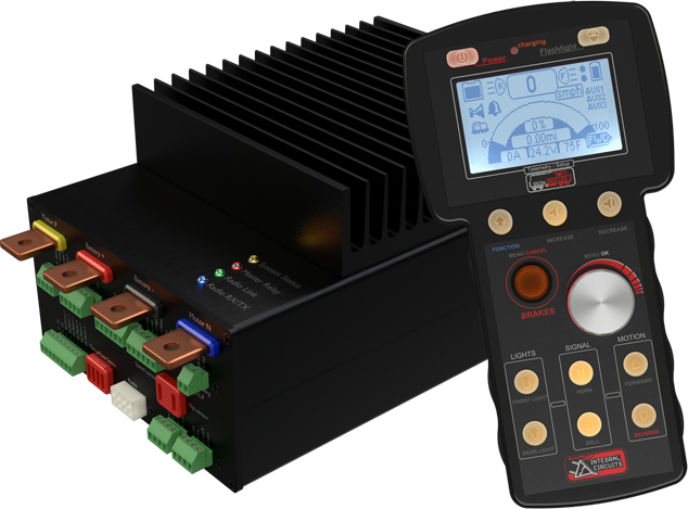
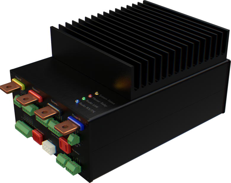
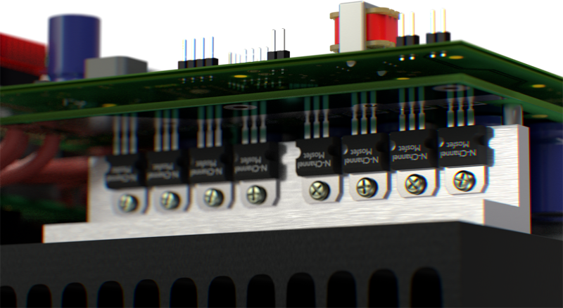
We use Quality parts to ensure a smooth and cool operation of our internal motor controller.

Great care has been taken to make sure our controller is sturdy and has a lot of headroom for current draw. Ensuring a prolonged continuous operation at 150A.

The Passive heatsink design with dual bank temperature sensing ensures a safe operation at peak performance without the need of a cooling fan. (operation with a fan can be done in cerctain circumstances)

Integrated per cycle overcurrent protection hardware limited to 175A ensures the controller will regulate the power to the motors in any overcurrent scenario, protecting the motor controller bridge and the motors.


Copyright 2017 Integral Circuits LLC.